Manufacturers have been able to save material costs. Simulations help them understand the amount of the material that is sufficient for the pre-defined boundary conditions, therefore, saving a lot of material and costs at the same time. Such designs consist of free forms that can only be manufactured using additive manufacturing technologies.
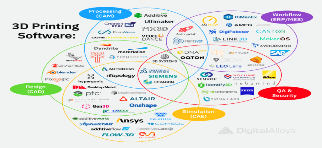
Designing components and doing topology optimization requires very robust knowledge of various CAD software and CAE packages as well. The image below shows some of the software packages one can use.

Awareness of the design rules for 3D printing is primarily an essential component to be able to design parts for topology optimization. These are some design rules that one can follow so as to be able to be successful in additive manufacturing. These include very important rules about the pin diameter, the tolerances, holes, horizontal bridges, embossing, supports, supported walls, and unsupported walls. Adhering to this will help succeed in designing components that are feasible for 3D printing. Another main element whose knowledge is the key component to designing components in 3D printing is DfAM which stands for Design for Additive Manufacturing. Laying your foundation in DfAM topics will help you design components that make sense to 3D printers. The image below shows certain rules for the same.

The inspiration for topology optimization can be taken from mother nature. Nature truly follows the concepts of topology optimization with the focus on just a sufficient amount of material that is required for the amount of load applied.


MSc Apex offers solutions for topology optimization. After the boundary conditions are applied it offers an intelligent smoothing option with consideration for manufacturability. Multiple designs can be generated at the end. The best part about MSc packages is the overall validation of the parts that can be done for manufacturability. Simufact offers the right solutions to validate the printability for all these designs that were developed.


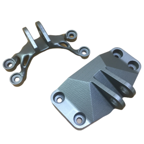
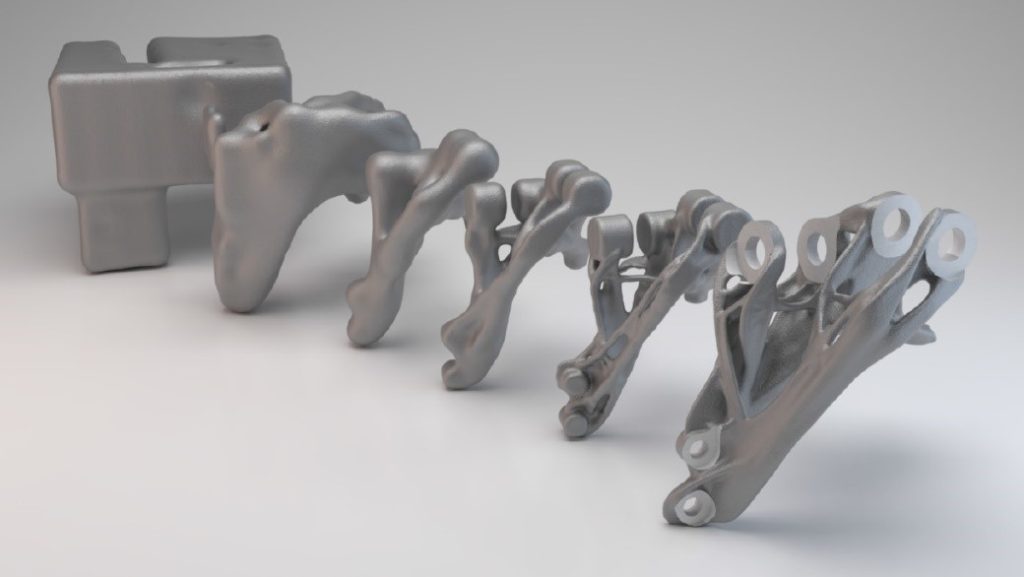
The above image shows a raw CAD model which is used directly for an application. The image shows the number of topologically optimized parts. You can see how much material is removed from the raw CAD data and only a sufficient amount of material is kept considering the loading conditions. Another image above showcases a best in class example of a topologically optimized part and how a 30% weight reduction was done.
Topology optimization is a tool that will assist the future of manufacturing technology. Various companies have already started implementing these parts in their final designs. Our expertise in Topology optimization has attracted projects from various companies in the automobile and space industries as well.
